Digital control design
Digital control loop structure
A common continuous closed-loop has the following structure:
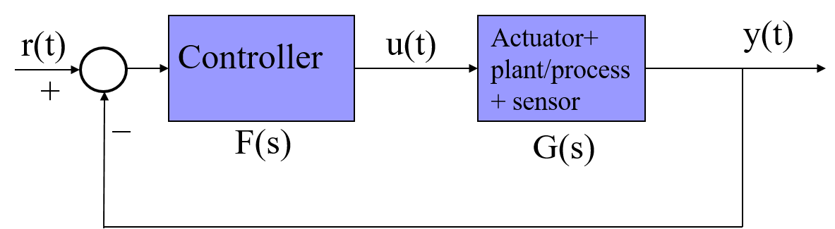
where all the elements are analog.
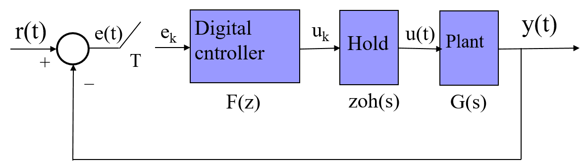
If we consider now a digital controller, the main closed-loop is:
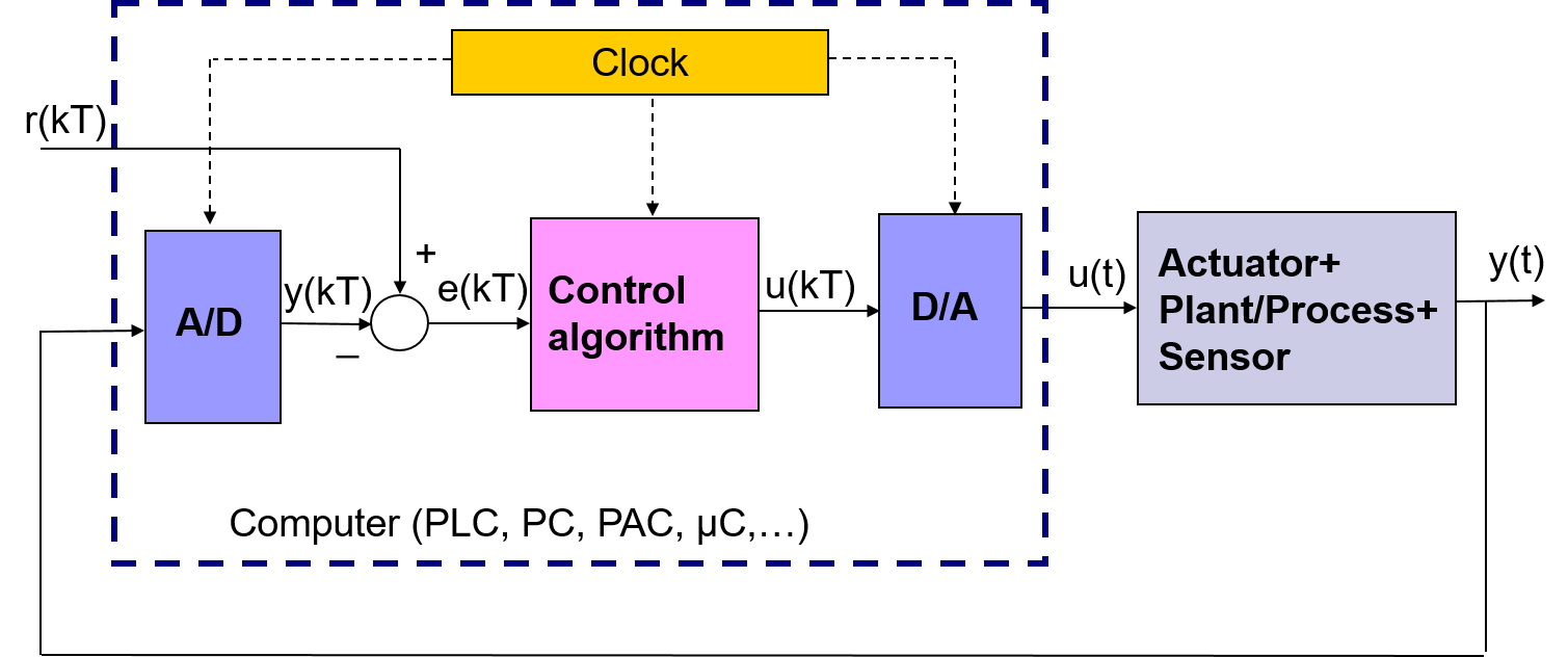
Now the loop contains both analog and digital signals. The implementation of the controller is done by means of a digital computer. The interface between analog and digital signals is done by the AD/DA converters:
A/D converter: sampling of the analog signals to convert it into a digital signal.
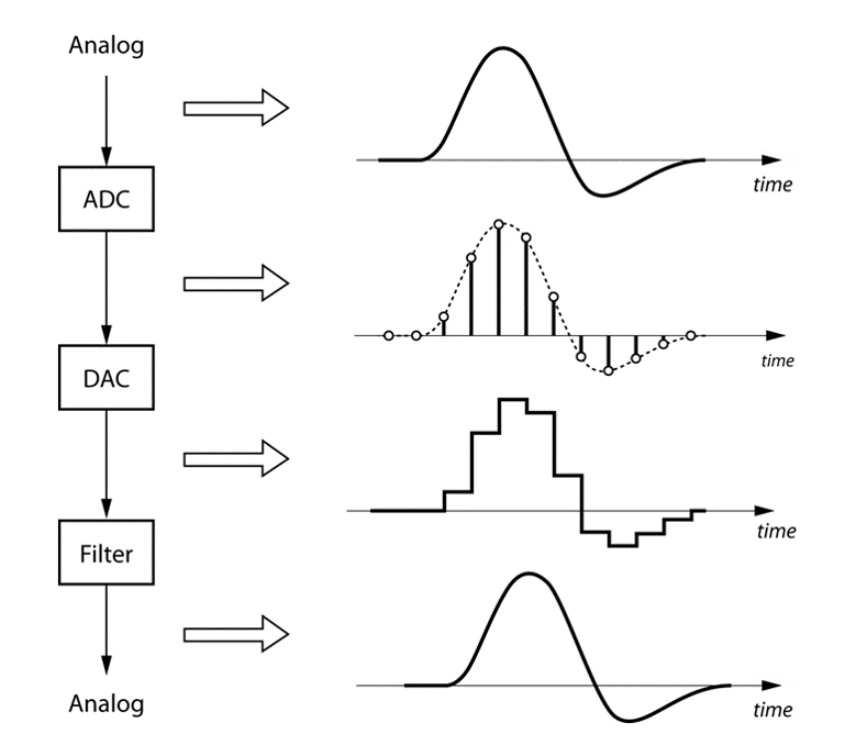
D/A converter: generation of an analog signal from a digital signal. Observe that apart from generating the analog values at he sample times, the D/A also provide values between sample times (so that a reconstruction of the signal is done). In general zero-order hold (zoh) is used for signal reconstruction. This element is based on mantaining the value of the last sample time until next sample time update. The transfer function of a zero order hold is:
An ilustration of the sampling and hold process is presented in the figure:
Analysis of a digital control loop
For the analysis of a digital control loop the following diagram can be considered:
If we focus the analysis on the output values at the sample-time intants, a sampling element should be included in the output:
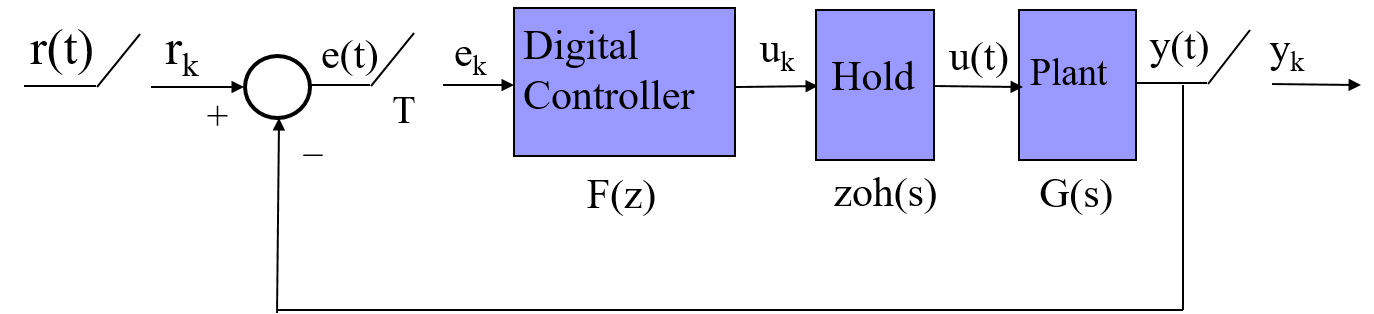
Or, equivalently:
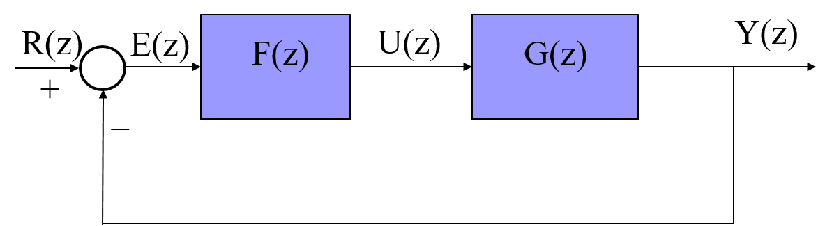
where

Implementation issues
Programming algorithm
The controller will be implmentes by means of a computer. The controller will be an executable program running in real-time. The algorithm is:
- Read the input variable y(kT) using a sensor/transmiter and the A/D converter.
- Compute the error e(kT)
- Obtain the control law u(kT) and send the resulting value to the actuator by means of the D/A converter.
- Update variables and execute storage actions if necessary.
- Wait until t=(k+1)t.
- k=k+1
- go to 1

Example: Obtaining the control law u(kT) for a simple transfer function |
|
|
Assume that the controller of a closed-loop system is
Obtain the control law u(kT).
|
|
Digital control design methodologies |
|
|
The video shows the different design approaches when designing a digital control system.
|
|
Discretization Methods
Different methods of discretization are available to calculate the approximate discrete equivalent model for a continuous model. Then, the objective is to obtain the discrete transfer function or difference equation or discrete state variable representation of a continuous system. Some of the most used methods are:
- Euler approximation: it is based on taking the differential equation and substituting the derivatives by difference approximations. Por example: dy(t)/dt ≈ (y(k)-y(k-1))/T.
- Bilinear transformation: it is based on taking G(s) and substituting s by

- Other approximations: impulse invariant approximation, step invariant approximation, ramp step invariant approximation.
Obra publicada con Licencia Creative Commons Reconocimiento No comercial Compartir igual 3.0